- Types of Sailboats
- Parts of a Sailboat
- Cruising Boats
- Small Sailboats
- Design Basics
- Sailboats under 30'
- Sailboats 30'-35
- Sailboats 35'-40'
- Sailboats 40'-45'
- Sailboats 45'-50'
- Sailboats 50'-55'
- Sailboats over 55'
- Masts & Spars
- Knots, Bends & Hitches
- The 12v Energy Equation
- Electronics & Instrumentation
- Build Your Own Boat
- Buying a Used Boat
- Choosing Accessories
- Living on a Boat
- Cruising Offshore
- Sailing in the Caribbean
- Anchoring Skills
- Sailing Authors & Their Writings
- Mary's Journal
- Nautical Terms
- Cruising Sailboats for Sale
- List your Boat for Sale Here!
- Used Sailing Equipment for Sale
- Sell Your Unwanted Gear
- Sailing eBooks: Download them here!
- Your Sailboats
- Your Sailing Stories
- Your Fishing Stories
- Advertising
- What's New?
- Chartering a Sailboat
- Righting Moment

The Righting Moment & Sailboat Stability
Feeling a sailboat heel under him for the first time, a novice sailor may wonder what stops it from going all the way over. The righting moment is, of course, t he reason why it doesn't .
Many years ago my son James asked me just that.
"It's that lump of lead in the keel" I explained.
"Why put lead in something you expect to float?" said James.
Hmm, perhaps he was onto something - I put him down as a future multihull man...
This piece of nostalgia hints at the two key ingredients to stability - ballast and hull form.
Monohulls have more of the first and less of the second, and multihulls very little of the first and much of the second.
And stability considerations fall under two further headings - static and dynamic. Static being when the boat is at rest; dynamic when underway and subject to the forces of wind and waves.
Righting Moment & Static Stability
Take a look at the sketches below:~
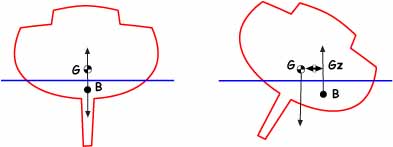
With the boat upright, the Centre of Gravity (G) is in line with the Centre of Buoyancy (B); effectively there is no righting moment.
But as the boat heels, a righting moment develops. The Moment Arm (Z) is the horizontal distance between G and B, and the Righting Moment Gz is the product of the moment arm and the boat's displacement.
But whilst the boat's displacement and the location of its Centre of Gravity remain constant, Z changes as the boat heals more and more. There comes a point at which Z reaches a maximum value, normally at an angle of heel of around 60 degrees or so. As the boat heels past this point it decreases, leading eventually to a capsize.
The relationship between heeling angle and righting moment is different for all boats, and the plotted Gz curve gives an excellent indicator of the boat's static stability.
But the boat's static stability and its righting moment is only part of the story. How will it react to a sudden gust of wind or when clobbered by a large wave?
Dynamic Stability
There's no arguing that heavy displacement helps a boat's stability, but the most important factor affecting dynamic stability is its moment of inertia. This is the measure of the boat's resistance to angular acceleration.
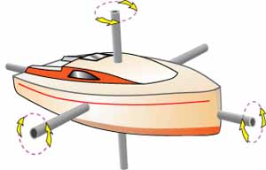
Boats rotate around three axes - rolling around the fore and aft axis; pitching about the transverse axis; yawing around the vertical axis.
It's the Roll Moment of Inertia (RMoI) that should concern us most as it's around the fore and aft axis that a boat is most likely to capsize.
This is calculated by multiplying the weight of all the boat's constituent parts by the square of the distance from the boat's Center of Gravity to the part's Center of Gravity - a tedious but necessary task for the designer. The squared term means that the distance of heavy items from the Center of Gravity greatly affect the RMoI, and the greater RMoI the less the boat will react to a gust of wind, or a large wave.
So boats with their ballast deep in their keels, their fuel and water tanks as far outboard as possible, and long heavy masts will have greater RMoI's and will be more dynamically stable as a result. Such boats will have long roll periods and will be highly resistant to rapid changes in heel angle.
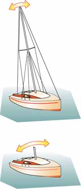
This will be very apparent to a crew unfortunate enough to have lost their rig, as this item is the boat's greatest contributor to the moment of inertia. Without it, the boat's roll period will be very quick and snappy, and the probability of capsize much higher.
Makers of grandfather clocks had cause to be grateful for the effects of the rotational moment of inertia. They used it to govern the rate of gain, or loss, of their creations.
To correct a 'slow' clock, the pendulum would be shortened slightly thereby reducing the distance to the neutral axis. This decreased the period of oscillation - it would swing faster - and speed up the clock's mechanism. Conversely, for a clock that gained, the pendulum would be increased in length to create the opposite effect.
The principal reason for using pendulums in clocks was that for a given length, the period of oscillation remains constant, irrespective of the amplitude.
Artwork by Andrew Simpson
And so it is with a boat; if she's rolling gently at anchor, or from gunwale to gunwale in a seaway, the roll period will be the same.
So clearly there's a lot more to a sailboat's stability than the Righting Moment alone.
Righting Moment & Stability: A Few FAQs...
What are some factors that affect the righting moment curve?
The righting moment curve is a graph that shows how the righting moment changes with different angles of heel. Some factors that affect this curve are:
- The displacement and distribution of weight of the boat, which determine the location and movement of the CG.
- The hull shape and volume of the boat, which determine the location and movement of the CB.
- The freeboard and deck shape of the boat, which affect when and how much water enters or leaves the boat as it heels, changing its buoyancy.
- The rigging and sail plan of the boat, which affect how much wind force and drag are applied to the boat at different angles of heel.
What are some advantages and disadvantages of having a high righting moment in a sailboat?
Some advantages of having a high righting moment are:
- The boat can carry more sail area and generate more speed and power in moderate winds.
- The boat can resist capsizing better in strong winds or waves.
- The boat can have a more comfortable motion and less fatigue for the crew in rough seas.
Some disadvantages of having a high righting moment are:
- The boat may have more wetted surface area and drag, reducing its speed and efficiency in light winds.
- The boat may have more weight and inertia, making it less responsive and manoeuvrable.
- The boat may have more cost and complexity in its design and construction.
What is the difference between righting moment and heeling moment?
The difference between righting moment and heeling moment is that they have opposite effects on the stability of a sailboat. Righting moment is the force that tries to restore the boat to its upright position, while heeling moment is the force that tries to tilt the boat away from its upright position.
The righting moment is determined by the distance between the centre of gravity (CG) and the centre of buoyancy (CB) of the boat, which changes as the boat heels.
The heeling moment is determined by the wind pressure on the sails and the water pressure on the hull, which also change as the boat heels.
A sailboat is stable when the righting moment is equal to or greater than the heeling moment, and unstable when the heeling moment is greater than the righting moment.
A sailboat can increase its righting moment by adding ballast, increasing beam, or reducing sail area, and can reduce its heeling moment by reefing, easing sheets, or changing course.
How does the wind speed affect the righting moment?
The wind speed affects the righting moment by changing the heeling moment, which is the force that tries to tilt the boat away from its upright position. The heeling moment is determined by the wind pressure on the sails and the water pressure on the hull, which also change as the boat heels.
The higher the wind speed, the higher the wind pressure on the sails, and the higher the heeling moment. This means that the boat will heel more for a given sail area and angle of attack. To counteract this, the boat needs to have a higher righting moment, which can be achieved by adding ballast, increasing beam, or reducing sail area.
The ideal wind speed for sailing depends on the type and size of the boat, the skill and preference of the sailor, and the weather and sea conditions. Generally, most sailors prefer a moderate wind speed of 5-12 knots, which allows them to sail comfortably and safely without excessive heeling or capsizing. However, some sailors may enjoy sailing in stronger winds of 15-25 knots, which can provide more speed and power, but also more challenge and risk.
How does the hull shape affect the righting moment?
he hull shape affects the righting moment by changing the position and movement of the centre of buoyancy (B) as the boat heels. The centre of buoyancy is the centroid of the boat's underwater volume, and the force of buoyancy acts upward through this point. The righting moment is the force that resists the heeling of the boat caused by the wind pressure on the sails. It is determined by the distance between the centre of gravity (G) and the centre of buoyancy (B) of the boat, which changes as the boat heels. Different hull shapes have different effects on the righting moment. Some examples are:
- A wide and shallow hull has more form stability, which means that it has a larger displacement of the centre of buoyancy to leeward as it heels. This increases the righting moment and makes the boat more stable, but also more prone to drag and less responsive.
- A narrow and deep hull has less form stability, which means that it has a smaller displacement of the centre of buoyancy to leeward as it heels. This decreases the righting moment and makes the boat less stable, but also more efficient and manoeuvrable.
- A round-bottomed hull has a low metacentric height, which means that it has a small distance between the centre of gravity and the metacentre (the point where a vertical line through the heeled centre of buoyancy intersects the ship's centreline). This makes the boat slow to roll and easy to overturn, but also more comfortable in rough seas.
- A flat-bottomed hull has a high metacentric height, which means that it has a large distance between the centre of gravity and the metacentre. This makes the boat quick to roll and hard to overturn, but also more uncomfortable in rough seas.
The above answers were drafted by sailboat-cruising.com using GPT-4 (OpenAI’s large-scale language-generation model) as a research assistant to develop source material; to the best of our knowledge, we believe them to be accurate.
Recent Articles
Passport 42 Sailboat Specs & Key Performance Indicators
Oct 09, 24 03:58 AM
Dufour 385 Grand Large Sailboat Specs & Key Performance Indicators
Oct 07, 24 11:03 AM
Used Sailboats for Sale in the Caribbean
Oct 02, 24 03:00 AM
Here's where to:
- Find Used Sailboats for Sale...
- Find Used Sailing Gear for Sale...
- List your Sailboat for Sale...
- List your Used Sailing Gear...
Our eBooks...

A few of our Most Popular Pages...
Copyright © 2024 Dick McClary Sailboat-Cruising.com

- News & Views
- Boats & Gear
- Lunacy Report
- Techniques & Tactics
MODERN SAILBOAT DESIGN: Quantifying Stability
We have previously discussed both form stability and ballast stability as concepts, and these certainly are useful when thinking about sailboat design in the abstract. They are less useful, however, when you are trying to evaluate individual boats that you might be interested in actually buying. Certainly you can look at any given boat, ponder its shape, beam, draft, and ballast, and make an intuitive guess as to how stable it is, but what’s really wanted is a simple reductive factor–similar to the displacement/length ratio , sail-area/displacement ratio , or Brewer comfort ratio –that allows you to effectively compare one boat to another.
Unfortunately, it is impossible to thoroughly analyze the stability of any particular sailboat using commonly published specifications. Indeed, stability is so complex and is influenced by so many factors that even professional yacht designers find it hard to quantify. Until the advent of computers, the calculations involved were so overwhelming that certain aspects of stability were only estimated rather than precisely determined. Even today, with computers doing all the heavy number crunching, stability calculations remain the most tedious part of a naval architect’s job.
There are, however, some tools available that you can use to make a sophisticated appraisal of a boat’s stability characteristics. If you dig and scratch a bit–on the Internet, or by pestering a builder or designer–you should be able to unearth one or more of them.
Stability Curves and Ratios
The most common tool used to assess a boat’s form and ballast stability is a stability curve. This is a graphic representation of a boat’s self-righting ability as it is rotated from right side up to upside down. Stability curves are sometimes published or otherwise made available by designers and builders, but to interpret them correctly, you first need to understand the physics of a heeling sailboat.
When perfectly upright, a boat’s center of gravity (CG)–which is a function of its total weight distribution (i.e., its ballast stability)–and its center of buoyancy (CB)–which is a function of its hull shape (i.e., its form stability)–are vertically aligned on the boat’s centerline. CG presses downward on the boat’s hull while CB presses upward with equal force. The two are in perfect equilibrium, and the boat is motionless. If some force heels the boat, however, CB shifts outboard of CG and the equilibrium is disturbed. The horizontal distance created between CG and CB as the boat heels is called the righting arm (GZ). This is a lever arm, with CG pushing down on one end and CB pushing up on the other, and their combined force, known as the righting moment (RM), works to rotate the hull back to an upright position. The point around which the hull rotates is known as the metacenter (M) and is always directly above CB.
The longer the righting arm (i.e., the larger the value for GZ), the greater the righting moment and the harder the hull tries to swing upright again. Up to a point, as a hull heels more, its righting arm just gets longer. The righting moment, consequently, gets larger and larger. This is initial stability. A wider hull has greater initial stability simply because its greater beam allows CB to move farther away from CG as it heels. Shifting ballast to windward also moves CG farther away from CB, and this too lengthens the righting arm and increases initial stability. The angle of maximum stability (AMS) is the angle at which the righting arm for any given hull is as long as it can be. This is where a hull is trying its hardest to turn upright again and is most resistant to further heeling.
Once a hull is pushed past its AMS, its righting arm gets progressively shorter and its ability to resist further heeling decreases. Now we are moving into the realm of ultimate, or reserve, stability. Eventually, if the hull is pushed over far enough, the righting arm disappears and CG and CB are again vertically aligned. Now, however, the metacenter and CG are in the same place, and the hull is metastable, meanings it is in a state of anti-equilibrium. Its fate hangs in the balance, and the least disturbance will cause it to turn one way or the other. This point of no return is the angle of vanishing stability (AVS). If the hull fails to right itself at this point, it must capsize. Any greater angle of heel will cause CG and CB to separate again, except now the horizontal distance between them will be a capsizing arm, not a righting arm. Gravity and buoyancy will be working together to invert the hull.
Stability at work. The righting arm (GZ) gets longer as the center of gravity (CG) and the center of buoyancy (CB) get farther apart, and the boat works harder to right itself. Past the angle of vanishing stability, however, the righting arm is negative and CG and CB are working to capsize the boat
A stability curve is simply a plot of GZ–including both the positive righting arm and the negative capsizing arm–as it relates to angle of heel from 0 to 180 degrees. Alternatively, RM (that is, both the positive righting moment and the negative capsizing moment) can be the basis of the plot, as it derives directly from GZ. (To find RM in foot-pounds, simply multiply GZ in feet by the boat’s displacement in pounds.) In either case, an S-curve plot is typical, with one hump in positive territory and another hopefully smaller hump (assuming the boat in question is a monohull) in negative territory.
The AMS is the highest point on the positive side of the curve; the AVS is the point at which the curve moves from positive to negative territory. The area under the positive hump represents all the energy that must be expended by wind and waves to capsize the boat; the area under the negative hump is the energy (usually only waves come into play here) required to right the boat again. To put it another way: the larger the positive hump, the more likely a boat is to remain right side up; the smaller the negative hump, the less likely it is to remain upside down.
Righting arm (GZ) stability curve for a typical 35-foot cruising boat. The angle of maximum stability (AMS) in this case is 55 degrees with a maximum GZ of 2.6 feet; the angle of vanishing stability (AVS) is 120 degrees; the minimum GZ is -0.8 feet
The relationship between the sizes of the two humps is known as the stability ratio. If you have a stability curve to work from, there are some simple calculations developed by designer Dave Gerr that allow you to estimate the area under each portion of the curve. To calculate the positive energy area (PEA), simply multiply the AVS by the maximum righting arm and then by 0.63: PEA = AVS x max. GZ x 0.63. To calculate the negative energy area (NEA), first subtract the AVS from 180, then multiply the result by the maximum capsizing arm (i.e., the minimum GZ) and then by 0.66: NEA = (180 – AVS) x min. GZ x 0.66. To find the stability ratio divide the positive area by the negative area.
Working from the curve shown in the graph above for a typical 35-foot cruising boat, we get the following values to plug into our equations: AVS = 120 degrees; max. GZ = 2.6 feet; min. GZ = -0.8 feet. The boat’s PEA therefore is 196.56 degree-feet: 120 x 2.6 x 0.63 = 196.56. Its NE is 31.68 degree-feet: (180 – 120) x -0.8 x 0.66 = 31.68. Its stability ratio is thus 6.2: 196.56 ÷ 31.68 = 6.2. As a general rule, a stability ratio of at least 3 is considered adequate for coastal cruising boats; 4 or greater is considered adequate for a bluewater boat. The boat in our example has a very healthy ratio, though some boats exhibit ratios as high as 10 or greater.
You can run these same equations regardless of whether you are working from a curve keyed to the righting arm or the righting moment. The curve in our example is a GZ curve, but if it were an RM curve, we only have to substitute the values for maximum and minimum RM for maximum and minimum GZ. Otherwise the equations run exactly the same way. The results for positive and negative area, assuming RM is expressed in foot-pounds, will be in degree-foot-pounds rather than degree-feet, but the final ratio will be unaffected.
GZ and RM curves are not, however, interchangeable in all respects. When evaluating just one boat it makes little difference which you use, but when comparing different boats you should always use an RM curve. Because righting moment is a function of both a boat’s displacement and the length of its righting arm, RM is the appropriate standard for comparing boats of different displacements. It is possible for different boats to have the same righting arm at any angle of heel, but they are unlikely to have the same stability characteristics. It always takes more energy to capsize a larger, heavier boat, which is why bigger boats are inherently more stable than smaller ones.
Righting moment (RM) stability curves for a 19,200-pound boat and a 28,900-pound boat with identical GZ values. Because heavier boats are inherently more stable, RM is the standard to use when comparing different boats (Data courtesy of Dave Gerr)
Another thing to bear in mind when comparing boats is that not all stability curves are created equal. There are various methods for constructing the curves, each based on different assumptions. The two most commonly used methodologies are based on standards promulgated by the International Measurement System (IMS), a once popular rating rule used in international yacht racing, and by the International Organization for Standardization (ISO). Many yacht designers have developed their own methods. When comparing different boats, you must therefore be sure their curves were constructed according to the same method.
Perfect Curves and Vanishing Angles
To get a better idea of how form and ballast relate to each another, it is useful to compare curves for hypothetical ideal vessels that depend exclusively on one type of stability or the other. A vessel with perfect form stability, for example, would be shaped very much like a wide flat board, and its stability curve would be perfectly symmetrical. Its AVS would be 90 degrees, and it would be just as stable upside down as right side up. A vessel with perfect ballast stability, on the other hand, would be much like a ballasted buoy–that is, a round, nearly weightless flotation ball with a long stick on one side to which a heavy weight is attached, like a pick-up buoy for a mooring or a man-overboard pole. The curve for this vessel would have no AVS at all; there would be just one perfectly symmetric hump with an angle of maximum stability of 90 degrees. The vessel will not become metastable until it reaches the ultimate heeling angle of 180 degrees, and no matter which way it turns at this point, it must right itself.
Ideal righting arm (GZ) stability curves: vessel A, a flat board, is as stable upside down as it is right side up; vessel B, a ballasted buoy, must right itself if turned upside down (Data courtesy of Danny Greene)
Beyond the fact that one curve has no AVS at all and the other has a very poor one, the most obvious difference between the two is that the board (vessel A) reaches its point of no return at precisely the point that the buoy (vessel B) achieves maximum stability. A subtler but critical difference is seen in the shape of the two curves between 0 and 30 degrees of heel, which is the range within which sailboats routinely operate. Vessel A achieves its maximum stability precisely at 30 degrees, and the climb of its curve to that point is extremely steep, indicating high initial stability. Vessel B, on the other hand, exhibits poor initial stability, as the trajectory of its curve to 30 degrees is gentle. Indeed, heeling A to just 30 degrees requires as much energy as is needed to knock B down flat to 90 degrees.
Righting arm (GZ) stability curves for a typical catamaran and a typical narrow, deep-draft, heavily ballasted monohull. Note similarities to the ideal curves in the last figure
To translate this into real-world terms, we need only compare the curves for two real-life vessels at opposite extremes of the stability spectrum. The curve for a typical catamaran, for example, looks similar to that of our board since its two humps are symmetrical. If anything, however, it is even more exaggerated. The initial portion of the curve is extremely steep, and maximum stability is achieved at just 10 degrees of heel. The AVS is actually less than 90 degrees, meaning that the cat, due to the weight of its superstructure and rig, will reach its point of no return even before it is knocked down to a horizontal position. The curve for a narrow, deep-draft, heavily ballasted monohull, by comparison, is similar to that of the ballasted buoy. The only significant difference is that the monohull has an AVS, though it is quite high (about 150 degrees), and its range of instability (that is, the angles at which it is trying to capsize rather than right itself) is very small, especially when compared to that of the catamaran.
The catamaran, due to its light displacement and great initial stability, will likely perform well in moderate conditions and will heel very little, but it has essentially no reserve stability to rely on when conditions get extreme. The monohull because of its heavy displacement (much of it ballast) and great reserve stability, will perform less well in moderate conditions but will be nearly impossible to overturn in severe weather.
What Is An Adequate AVS?
In the real world you will rarely come across stability curves for catamarans. If you do find one, you should probably be most interested in the AMS and the steepness of the curve leading up to it. Monohull sailors, on the other hand, should be most interested in the AVS, and as a general rule the bigger this is the better.
Coastal cruisers sailing in protected waters should theoretically be perfectly safe in a boat with an AVS of just 90 degrees. Assuming you never encounter huge waves, the worst that could happen is you will be knocked flat by the wind, and so as long as you can recover from a 90-degree knockdown, you should be fine. It’s nice to have a safety margin, however, so most experts advise that average-size coastal cruising boats should have an AVS of at least 110 degrees. Some believe the minimum should 115 degrees.
For offshore sailing you want a larger margin of safety. Recovering from a knockdown in high winds is one thing, but in a survival storm, with both high winds and large breaking waves, there will be large amounts of extra energy available to help roll your boat past horizontal. There is near-universal consensus that bluewater boats less than 75 feet long should have an AVS of at least 120 degrees. Because larger boats are inherently more stable, the standard for boats longer than 75 feet is 110 degrees.
The reason 120 degrees is considered the minimum AVS standard for most bluewater boats is quite simple. Naval architects figure that any sea state rough enough to roll a boat past 120 degrees and totally invert it will also be rough enough to right it again in no more than 2 minutes. This, it is assumed, is the longest time most people can hold their breaths while waiting for their boats to right themselves. If you don’t ever want to hold your breath that long, you want to sail offshore in a boat with a higher AVS.
Estimated times of inversion for different AVS values (Data courtesy of Dave Gerr)
As this graph illustrates, an AVS of 150 degrees is pretty much the Holy Grail. A boat with this much reserve stability can expect to meet a wave large enough to turn it right side up again almost the instant it’s turned over.
Other Factors To Consider
Stability curves may look dynamic and sophisticated, but in fact they are based on relatively simple formulas that can’t account for everything that might make a particular boat more or less stable in the real world. For one thing, as with regular performance ratios, the displacement values used in calculating stability curves are normally light-ship figures and do not include the weight that is inevitably added when a boat is equipped and loaded for cruising. Even worse, much of this extra weight–in the form of roller-furling units, mast-mounted radomes, and other heavy gear–will be well above the waterline and thus will erode a boat’s inherent stability. The effect can be quite large. For example, installing an in-mast furling system may reduce your boat’s AVS by as much as 20 degrees. In most cases, you should assume that a loaded cruising boat will have an AVS at least 10 degrees lower than that indicated on a stability curve calculated with a light-ship displacement number.
Another important factor to consider is downflooding. Stability curves normally assume that a boat will take on no water when knocked down past 90 degrees, but this is unlikely in the real world. The companionway hatch will probably be at least partway open, and if the knockdown is unexpected, other hatches may be open as well. Water entering a boat that is heeled to an extreme angle will further destabilize the boat by shifting weight to its low side. If the water sloshes about, as is likely, this free-surface effect will make it even harder for the boat to come upright again.
This may seem irrelevant if you are a coastal cruiser, but if you are a bluewater cruiser you should be aware of the location of your companionway. A centerline companionway will rarely start downflooding until a boat is heeled to 110 degrees or more. An offset companionway, however, if it is on the low side of the boat as it heels, may yield downflood angles of 100 degrees or lower. A super AVS of 150 degrees won’t do much good if your boat starts flooding well before that. To my knowledge, no commonly published stability curve accounts for this factor.
Another issue is the cockpit. An open-transom cockpit, or a relatively small one with large effective drains, will drain quickly if flooded in a knockdown. A large cockpit that drains poorly, however, may retain water for several minutes, and this, too, can destabilize a boat that is struggling to right itself.
This boat has features that can both degrade and improve its stability. The severely offset companionway makes downflooding a big risk during a port tack knockdown or capsize, but the high rounded cabintop and small cockpit footwell will help the boat to right itself
Fortunately, not all unaccounted for stability factors are negative. IMS-based stability curves, for example, assume that all boats have flush decks and ignore the potentially positive effect of a cabin house. This is important, as a raised house, particularly one with a rounded top, provides a lot of extra buoyancy as it is submerged and can significantly increase a boat’s stability at severe heel angles. Lifeboats and other self-righting vessels have high round cabintops for precisely this reason.
ISO-based stability curves do account for a raised cabin house, but not all designers believe this is a good thing. A cabin house only increases reserve stability if it is impervious to flooding when submerged. If it has open hatches or has large windows and apertures that may break under pressure, it will only help a boat capsize and sink that much faster. The ISO formulas fail to take this into account and instead may award high stability ratings to motorsailers and deck-saloon boats with large houses and windows that may be vulnerable in extreme conditions.
Simplified Measures of Stability
In addition to developing stability curves, which obviously are fairly complex, designers and rating and regulatory authorities have also worked to quantify a boat’s stability with a single number. The simplest of these, the capsize screening value (CSV), was developed in the aftermath of the 1979 Fastnet Race. Over a third of the more than 300 boats entered in that race, most of them beamy, lightweight IOR designs, were capsized (rolled to 180 degrees) by large breaking waves, and this prompted a great deal of research on yacht stability. The capsize screening value, which relies only on published specifications and was intended to be accessible to laypeople, indicates whether a given boat might be too wide and light to readily right itself after being overturned in extreme conditions.
To figure out a boat’s CSV divide the cube root of its displacement in cubic feet into its maximum beam in feet: CSV = beam ÷ ³√DCF. You’ll recall that a boat’s weight and the volume of water it displaces are directly related, and that displacement in cubic feet is simply displacement in pounds divided by 64 (which is the weight in pounds of a cubic foot of salt water). To run an example of the equation, let’s assume we have a hypothetical 35-foot boat that displaces 12,000 pounds and has 11 feet of beam. To find its CSV, first calculate DCF–12,000 ÷ 64 = 187.5–then find the cube root of that result: ³√187.5 = 5.72; note that if your calculator cannot do cube roots, you can instead take 187.5 to the 1/3 power and get the same result. Divide that result into 11, and you get a CSV of 1.92: 11 ÷ 5.72 = 1.92.
Interpreting the number is also simple. Any result of 2 or less indicates a boat that is sufficiently self-righting to go offshore. The further below 2 you go, the more self-righting the boat is; extremely stable boats have values on the order of 1.7. Results above 2 indicate a boat may be prone to remain inverted when capsized and that a more detailed analysis is needed to determine its suitability for offshore sailing.
As handy as it is, the CSV has limited utility. It accounts for only two factors–displacement and beam–and fails to consider how weight is distributed aboard a boat. For example, if we load our hypothetical 12,000-pound boat with an extra 2,250 pounds for light coastal cruising, its CSV declines to 1.8. Load it with an extra 3,750 pounds for heavy coastal or moderate bluewater use, and the CSV declines still further, to 1.71. This suggests that the boat is becoming more stable, when in fact it may become less stable if much of the extra weight is distributed high in the boat.
Note too that a boat with unusually high ballast–including, most obviously, a boat with ballast in its bilges rather than its keel–will also earn a deceptively low screening value. Two empty boats of identical displacement and beam will have identical screening values even though the boat with deeper ballast will necessarily be more resistant to capsize.
Another single-value stability rating still frequently encountered is the IMS stability index number. This was developed under the IMS rating system to compare stability characteristics of race boats of various sizes. The formula essentially restates a boat’s AVS so as to account for its overall size, awarding higher values to longer boats, which are inherently more stable. IMS index numbers normally range from a little below 100 to over 140. For what are termed Category 0 races, which are transoceanic events, 120 is usually the required minimum. In Category 1 events, which are long-distances races sailed “well offshore,” 115 is the common minimum standard, and for Category 2 events, races of extended duration not far from shore, 110 is normally the minimum standard. Conservative designers and pundits often posit 120 as the acceptable minimum for an offshore cruising boat.
Since many popular cruising boats were never measured or rated under the IMS rule, you shouldn’t be surprised if you cannot find an IMS-based stability curve or stability index number for a cruising boat you are interested in. You may find one if the boat in question is a cruiser-racer, as IMS was once a prevalent rating system. Bear in mind, though, that the IMS index number does not take into account cabin structures (or cockpits, for that matter), and assumes a flush deck from gunwale to gunwale. Neither does it account for downflooding.
Another single-value stability rating that casts itself as an “index” is promulgated by the ISO. This is known as STIX, which is simply a trendy acronym for stability index. Because STIX values must be calculated for any new boat sold inside the European Union (EU), and because STIX is, in fact, the only government-imposed stability standard in use anywhere in the world, it is likely to become the predominant standard in years to come.
A STIX number is the result of many complex calculations accounting for a boat’s length, displacement, beam, ability to shed water after a knockdown, angle of vanishing stability, downflooding, cabin superstructure, and freeboard in breaking seas, among others. STIX values range from the low single digits to about 50. A minimum of 38 is required by the European Union for Category A boats, which are certified for use on extended passages more than 500 miles offshore where waves with a maximum height of 46 feet may be encountered. A value of at least 23 is required for Category B boats, which are certified for coastal use within 500 miles of shore where maximum wave heights of 26 feet may be encountered, and the minimum values for categories C and D (inshore and sheltered waters, respectively) are 14 and 5. These standards do not restrict an owner’s use of his boat, but merely dictate how boats may be marketed to the public.
The STIX standard has many critics, including many yacht designers who do not enjoy having to make the many calculations involved, but the STIX number is the most comprehensive single measure of stability now available. As such, it can hardly be ignored. Many critics assert that the standards are too low and that a number of 40 or greater is more appropriate for Category A boats and 30 or more is best for Category B boats. Others believe that in trying to account for and quantify so many factors in a single value, the STIX number oversimplifies a complex subject. To properly evaluate stability, they suggest, it is necessary to evaluate the various factors independently and make an informed judgment leavened by a good dose of common sense.
As useful as they may or may not be, STIX numbers are generally unavailable for boats that predate the EU’s adoption of the STIX standard in 1998. Even if you can find a number for a boat you are interested in, bear in mind that STIX numbers do not account for large, potentially vulnerable windows and ports in cabin superstructures, nor do they take into account a boat’s negative stability. In other words, boats that are nearly as stable upside down as right side up may still receive high STIX numbers.
The bottom line when evaluating stability is that no single factor or rating should be considered to the exclusion of all others. It is probably best, as the STIX critics suggest, to gather as much information from as many sources as you can, and to bear in mind all we have discussed here when pondering it.
Related Posts

- BAYESIAN TRAGEDY: An Evil Revenge Plot or Divine Justice???
Extremely good analysis of the issue. Did you do an engineering degree before law school Charlie? One more thought on stability that is outwith the scope of the indices. In the classic broach, as the vessel rounds up th keel bites the water and makes the turn worse, increasing the apparent wind and angle of heel, making the rudder progressively less effective,until it is powerless at 90 degrees heel. In a centreboarder with the board up, the bow skids off, avoiding a real broach, and hence danger of being forced to the spreaders hitting the water. We were caught in a 25 knot gust with our somewhat oversize spi up, the helmsman fell and let go, yet we never heeled past about 50 degrees. You had some fun on the cboard Che Vive in strong wind from aft. To some extent, this phenomenon mitigates the poorer AVS of the centreboarder. Is it enough? I hope to avoid checking it out in practice
@Neil: You’re right. I think centerboard boats are more stable in some situations, less stable in others, and the situations in which they are more stable are not represented in stability curves. It is an imperfect science, to say the least. For example, a point I probably should have emphasized a bit more strongly in the text is that the capsize screening value was never ever intended to be dispositive. It was only intended to identify boats that should be subjected to a more rigorous analysis. Thus the word “screening.” charlie
Charlie just came across this post while preparing for my next workshop this weekend. It’s flat out great, the best real world explanation of stability I’ve read.
John, Im John. I live in Rural N.C. about 75 minutes inland from New Bern. Im 58, single dad and when my 17 year old graduates next year i will be headed to Thailand….from North Carolina. I will NOT see the Cape to starboard…maybe i will write a book…Panama to Starboard
@John: Coming from you, that’s a real compliment. Thanks, mate!
A bit late in the day given the date of the article. Anyway here goes. The boat properties in this article are obtained under static equilibrium conditions. Thus the moment resistance curve is obtained by calculating the relative positions of the weight of the vessel and the buoyancy force as the hull is caused to rotate or heel- the resistance due to the moment produced by the misalignment of the two forces at various angles of heel. Because the movement takes place extremely slow no account is allowed for the effect of inertia. I would like to make my point my considering the example of a bag of sugar : In the first example (a) the sugar is gently poured from the bag onto the pan of a weigh scale until the required weight is reached , say one pound: thus an oz at a time until the scale pointer is at one pound ! In case (b) the sugar is placed in a bag, and the bag is placed in contact with the scale but then suddenly released. At which point the scale pointer will swing well past the 1 pound mark reaching 2 pounds , and the pointer will oscillate about the one pound mark, eventually coming to rest about this value! In case (c) the bag , instead of being placed in contact with pan is released from a height of one foot before being released. This will cause likely cause the pointer to be bent and a broken weigh scale.
It is a apparent that the properties used to measure a boats stability are derived from the conditions similar to case (a), while in reality they should be deduced from case (c) INERTIA IS IMPORTANT.
Leave a Reply Cancel Reply
Save my name, email, and website in this browser for the next time I comment.
Please enable the javascript to submit this form

Recent Posts
- LES ENFANTS DU LARGE: Virginia Tangvald’s Fantastic Film About Her Brother Thomas and Father Peter
- ME AND SIR FRANCIS: Bursitis; Coastal Dog Cruise; Innovation at IBEX
- MAINTENANCE & SUCH: July 4 Maine Coast Mini-Cruz
- SAILGP 2024 NEW YORK: Lifestyles of the Rich and Famous
Recent Comments
- David Dalmau on NICK SKEATES ON WYLO II: The Ultimate Barebones Cruiser and his Ultimate Dirt Simple Boat
- Charles Doane on FREE SWAN 48: More Info And A Plan
- AJ Smith on FREE SWAN 48: More Info And A Plan
- Angela on GROOTE BEER: Hermann Goering’s Botter Jacht (Not)
- Gweilo on SWAN 48 SALVAGE ATTEMPT: Matt Rutherford Almost Got Ripped Off! (IMHO)
- October 2024
- August 2024
- January 2024
- December 2023
- November 2023
- October 2023
- September 2023
- August 2023
- February 2023
- January 2023
- December 2022
- November 2022
- September 2022
- August 2022
- February 2022
- January 2022
- December 2021
- November 2021
- October 2021
- September 2021
- February 2021
- January 2021
- December 2020
- November 2020
- October 2020
- September 2020
- August 2020
- February 2020
- January 2020
- December 2019
- November 2019
- October 2019
- September 2019
- August 2019
- January 2019
- December 2018
- November 2018
- October 2018
- September 2018
- August 2018
- February 2018
- January 2018
- December 2017
- November 2017
- October 2017
- September 2017
- August 2017
- February 2017
- January 2017
- December 2016
- November 2016
- October 2016
- September 2016
- August 2016
- February 2016
- January 2016
- December 2015
- November 2015
- October 2015
- September 2015
- August 2015
- February 2015
- January 2015
- December 2014
- November 2014
- October 2014
- September 2014
- August 2014
- February 2014
- January 2014
- December 2013
- November 2013
- October 2013
- September 2013
- August 2013
- February 2013
- January 2013
- December 2012
- November 2012
- October 2012
- September 2012
- August 2012
- February 2012
- January 2012
- December 2011
- November 2011
- October 2011
- September 2011
- August 2011
- February 2011
- January 2011
- December 2010
- November 2010
- October 2010
- September 2010
- August 2010
- February 2010
- January 2010
- December 2009
- October 2009
- Boats & Gear
- News & Views
- Techniques & Tactics
- The Lunacy Report
- Uncategorized
- Unsorted comments

- Measurements
On this page
Stability measurements give important hydrostatic and stability data necessary for determining elements of both performance and safety. The results of a stability test gives a boat's righting moment, vertical centre of gravity (VCG) and limit of positive stability (LPS), which with the Stability Index (SI) can help determine a boat's eligibility to enter races categorized according to the WS Offshore Special Regulations.
Freeboard measurements give a boat's waterline in measurement trim from which displacement, wetted surface and overhangs are calculated from the hull shape defined in the offset filet. Freeboards are measured at freeboard points identified in the hull offset file together with specific gravity of the water that equalize displacement calculation for boats measured in fresh water with those measured at the sea.

Inclining test
An inclining test is performed on a boat in measurement trim while floating in calm water and not affected on any side by lying to a mooring, and with no one aboard.
- Two poles are simultaneously positioned on port and starboard sides, at defined position (approximately at the longitudinal centre of flotation)
- The poles are suspended outboard to provide arms for supporting weights and arranged to be perpendicular to the boat’s centreline and as horizontal as possible but still allowing sufficient clearance to prevent the weights from touching the water.
- Either a manometer or an ORC-approved electronic inclinometer is placed on the deck and positioned athwart the boat where it can be read by the measurer.
- Weights, depending on the size of the boat, are suspended on one the pole on port side and resulting heel angle is recorded.
- Half of total weight is suspended at the same time on the port in starboard sides so that the total distance between weights can be measured.
- All weights are then suspended on starboard side and resulting heel angle is recorded again.
Alternatively to the procedure defined above and particularly on boats that would require heavier weights to be suspended, a boat’s boom may be used to suspend weights as follows:
- The boom is placed outboard and fixed to the shrouds.
- Heel angle without weights is be recorded either with a manometer or an ORC-approved electronic inclinometer
- Weights are suspended on the end of the boom and resulting angle recorded again either with a manometer or an ORC-approved electronic inclinometer.
- Same procedure is repeated on port and starboard sides, averaging the results
- Longitudinal position of the weight and distance from the boat’s centerline is measured on both sides.
From the resulting heel angle, the amount of weight and the distance between weights it is possible to calculate the position of the vertical centre of gravity and the complete set of hydrostatic and stability data for the boat. A stability curve can then be calculated showing the righting arm against heel angle. The important point on that curve is the angle when the righting arm is equal to 0, called LPS (limit of positive stability) or AVS (angle of vanishing stability). This means that if the boat is heeled at that angle from an upright position it will still return to being upright, while beyond this angle the boat will capsize.

For boats with a canting keel, an inclining test is performed with the keel on centerline. After the keel is fully-canted the resulting heel is recorded so that the effect of the canting keel on the boat's stability can be calculated.
Offshore Racing Congress Partners
Log in to ORC Sailor services using email and password
ORC Sailor Services allows you access to ORC Database of all ORC certificates issued worldwide such as accessing speed guides, target speeds and do test runs on any certificate.
ORC Sailor Services - Password reminder
Please enter the e-mail address registered for the ORC Sailor Services to receive your password
ORC Sailor Services
With an ORC Certificate you are getting more than just a rating. ORC Sailor Services allows you access to the ORC Database of all ORC certificates issued worldwide.
- New Sailboats
- Sailboats 21-30ft
- Sailboats 31-35ft
- Sailboats 36-40ft
- Sailboats Over 40ft
- Sailboats Under 21feet
- used_sailboats
- Apps and Computer Programs
- Communications
- Fishfinders
- Handheld Electronics
- Plotters MFDS Rradar
- Wind, Speed & Depth Instruments
- Anchoring Mooring
- Running Rigging
- Sails Canvas
- Standing Rigging
- Diesel Engines
- Off Grid Energy
- Cleaning Waxing
- DIY Projects
- Repair, Tools & Materials
- Spare Parts
- Tools & Gadgets
- Cabin Comfort
- Ventilation
- Footwear Apparel
- Foul Weather Gear
- Mailport & PS Advisor
- Inside Practical Sailor Blog
- Activate My Web Access
- Reset Password
- Customer Service

- Free Newsletter

Tartan 37 Used Boat Review

C&C 33 Mark II Used Boat Review
Island Packet 350 Used Boat Review
Beneteau 393 Used Boat Review

How to Create a Bullet-Proof VHF/SSB Backup

Tips From A First “Sail” on the ICW

Tillerpilot Tips and Safety Cautions

Best Crimpers and Strippers for Fixing Marine Electrical Connectors
Are Wrinkles Killing Your Sail Shape?
Superlight Anchors: Not Just for Racers
Refining Furling Line Fairleads

Revive Your Mast Like a Pro

Diesel-Electric Hybrids Vs. Electric: Sailing’s Auxiliary Power Future
Sailing Triteia: Budget Bluewater Cruising
How To Keep Pipe Fittings Dry: Sealant and Teflon Tape Tests

How Much Does it Cost to Own a Sailboat in Quebec,…
Anode Basics: Dos and Don’ts

What’s The Best Bottom Paint?
Boat Hook and Fender Hacks

Product Hacks: Velcro, Bounce, Anti-Skid Mats and Pool Lights

Stopping Holding-tank Odors
Giving Bugs the Big Goodbye

Galley Gadgets for the Cruising Sailor

Cold Weather Clothes to Extend the Sailing Season

Five Best Gloves: Sailing and DIYing in All Weather

Sailing Gear for Kids

What’s the Best Sunscreen?

R. Tucker Thompson Tall Ship Youth Voyage

On Watch: This 60-Year-Old Hinckley Pilot 35 is Also a Working…
On Watch: America’s Cup
On Watch: All Eyes on Europe Sail Racing

Dear Readers
- Safety & Seamanship
DIY Stability Check?
There are no quick answers to stability questions..

When the waves kick up, you can’t help thinking about ultimate stability. Am I feeling form stability, the stability that relies on the boat’s beam and buoyancy to resist healing? Or is it the counteracting righting moment of ballast that is keeping the boat upright? Except for unballasted racing dinghies, it’s a bit of both.
Last month, we discussed multihull stability and how both form stability (weight and beam) and dynamic stability (burying of hulls and bows) affect our ability to stay right-side up (see “ Multihull Capsize Risk Check, ” February 2021). In “ Dissecting the Art of Staying Upright ,” Practical Sailor June 2015 we discussed the GZ curve and the limit of positive stability (LPS), also called the angle of vanishing stability (AVS). We’ll review these briefly here, but for those unfamiliar with the topic of stability, it would be good to review our past articles on stability first.
Modern production boats ISO CE category certifications that are supposed to indicate their suitability for sea. Boats rated for Category A “Offshore,” and Category B “Ocean,” must also meet the latest version of the International Stability Standard IS0 12217, which specifies stability based on the boat’s mass and its AVS. Our aim with this report was to address a perennial stability question. Can an owner create a GZ curve and or determine the AVS for custom boats, modified boats or older boats that lack CE certificates or published data?
The GZ Curve
The factors involved in determining the GZ curve, or righting moment curve, is pretty straightforward. Righting moment at any given angle of heel is defined as the force applied at some distance from the heeled center line times the distance from the heeled centerline. For example, if it takes 200 pounds on the rail (6 feet from the centerline in this example) to heel a boat 5 degrees, the righting moment at 5 degrees is 200 x 6 = 1,200 ft-pounds.
In most boats the righting moment rises from zero at rest, to a maximum AVS of about 40-80 degrees of heel. Ballasted keelboats can extend that significantly.
As pointed out in the June 2015 report, it is important to understand that stability is not the same as seaworthiness. Stability is but one item of compliance among many (such as hatch area and placement) used to determine a boat’s ISO CE category. The GZ curve ignores the very significant effect of sloping or breaking waves. Cabin flooding, cockpit flooding, crew movement, gear shifting, and free surface movement of liquids in tanks are also neglected.
Any of these factors can have significant impact on stability, and will greatly reshape a boat’s “real world” GZ curve. Also, as we discussed in our September 2015 PS Advisor column, things like davits, dodgers, and in-mast furling can render obsolete your maker’s stability specs.
What does a desirable GZ curve look like? What AVS or LPS do we aim for? According to the World Offshore Special Regulations, racers will not be issued a valid racing certificate for World Sailing races if the boat’s upper limit of positive stability is less than 103 degrees (90 degrees for ORC sport boat), as measured per IS0 12217-2.
Practical Sailor recommends a minimum of 120 degrees for cruising monohulls. Boats certified by the ORC (Offshore Racing Congress) have had the shape of their GZ curve evaluated by computer, based on data obtained while taking precise measurements while heeling the boat with weights in calm conditions. The measurements help determine the center of gravity of the boat, the shape of the GZ curve, and the limit of positive stability.
With or without the involvement of a naval architect, getting accurate GZ Curve using an incline test is not the sort of thing a typical DIY sailor is usually capable of handling.
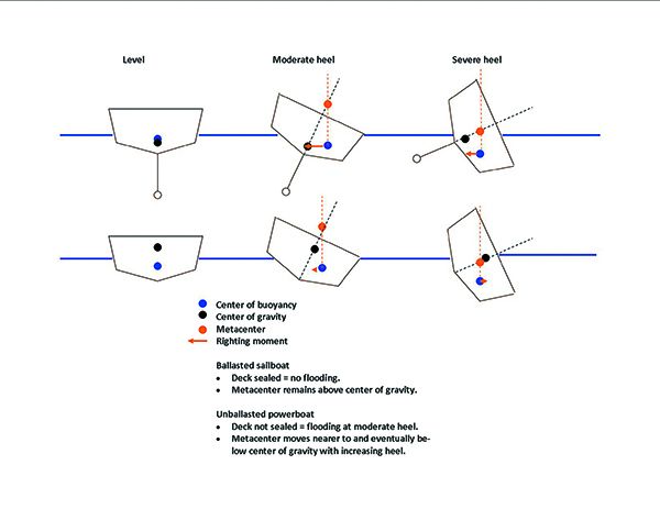
The simplified (ISS) method does a fair job of predicting the stability of unballasted powerboats, but not ballasted sailboats. At 10-15 degrees of heel the hulls are similar, but at extreme angles they are very different. A 5-10 degree heel on a powerboat reveals a lot about stability, but with a sailboat, we want to know the maximum righting moment (probably between 40-80 degrees), and the angle of no return (limit of positive stability), which probably occurs with the mast deep underwater. The shape of the GZ Curve becomes clear only after a boat is heeled close to the maximum righting moment.
The Westlawn approach
The high-profile capsize of a number of small passenger pontoon ferries in the U.S. has prompted a search for a simplified stability testing process that the U.S. Coast Guard could apply to small commercial passenger boats. Like IS0 CE 12217, the current Coast Guard method of evaluating stability is complex, requiring detailed hull form and construction data, and calculations based on the relationship between the center of gravity, center of buoyancy, and the heeled metacenter. These measurements are not readily available for many boats, and any changes to the boat’s design or operations (number, or placement of passengers) can make the original numbers wildly inaccurate.
In 2009 the Westlawn Institute of Marine Technology proposed a simplified method of stability testing. The boat would be heeled as much as 15 degrees using weights, avoiding some of the need for detailed knowledge of buoyancy and weight distribution. This would be called the Inland Stability Standard (ISS).
ISS and Wind Heel
According to the ISS, heel induced by wind alone “wind heel” should not immerse more than ¼ to ½ of freeboard in the strongest expected wind, and the heel angle should not be more than 14 degrees. The strongest wind that you’ll use for calculation varies depending upon whether you are in exposed waters or protected waters. This is based on CFR 170.170.
The extent of freeboard immersion varies with the amount of floodable cockpit; a boat with a sealed cockpit can safely heel farther than one with a large open cockpit.
In exposed waters:
Immersion limit =
f(2LOD-1.5CL)/4 x LOD
In protected waters
(2 x f x LOD-CL)/4 x LOD
f means freeboard
CL means cockpit length
LOD means length on deck
Heel angle = (wind pressure)(average distance from center of windage to center of resistance)(53.7) /((GM)(displacement in pounds))
Center of lateral resistance (CLR) is estimated to be about ½ draft.
GM is the metacentric height
The wind pressure variable used will depend on sailing area :
For an ocean crossing = 50 knots or 15 pounds/square foot
For ocean coastal = 45 knots or 13.4 pounds/square foot
For semi-protected waters = 40 knots or 8.5 pounds/square foot
For protected waters = 35 knots or 6.5 pounds/square foot
Passenger heel
According to the ISS, the passenger heel limit (with all passengers shifted to one side) should not exceed ¼ of total freeboard—or ½ of freeboard if the deck is sealed or the cockpit is very small. Heel angle should never be more than 14 degrees with all of the passengers shifted to one side of the boat. This is based on US CFR 171.50. The average passenger weight in CFR 171.50 is estimated as 140, but it will likely be adjusted upward in future revisions.
Passenger heel angle = arcsin((2/3 of passengers x ½ beam)/(Displacement x GM))(Arcsin is on your smart phone calculator).
Displacement is the weight of the boat in pounds with fuel and water but without passengers, and
GM means metacentric height
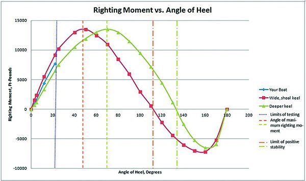
As we discussed in our 2015 report “Dissecting the Art of Staying Upright,” the GZ Curve (at right) can be used to calculate a stability ratio—the area circumscribed in the positive portion of the curve, divided by the area circumscribed by the negative portion of the curve. A higher ratio is better, and a common rule of thumb is that an ocean voyaging boat should have a ratio above 3.0.
The main article discusses creating a partial table based on heeling angles. Heeling a boat beyond 20 degrees is tricky, but if you can find boats with comparable design features and known GZ-Curves, you can visualize your own righting moment at various angles of heel, or at least roughly check the angle of maximum righting moment and the limit of positive stability. In the example case, “your boat” would likely meet or exceed the minimum LPS we recommend for offshore sailing (120 degrees), but without more information one can’t know for certain.
Once you have collected the data from your boat and other boats, you can create your own table using Microsoft Excel. Here’s how we do it.

- Create a table like the adjacent table with angle and moment in columns. Although we have entered units of measure (ft.-lbs.) do not include them in your table at this time. Place any columns used for intermediate calculations (unit conversions and heel angle) to the right and do not highlight these in the graphing process.
- Highlight and select the cells containing angle of heel, righting moment., and the associated headers.
- Click “insert” on the top tool bar, and then click “scatter” from the graphing options. This will accommodate angles at irregular intervals.
- Click “Design” and a dialogue box will let you chose the title style you want. You will also be able to enter the units and descriptions for each axis.
- You can save the graph as a PDF by selecting the graph and choosing PDF on the “save as” file type menu.
Finding Metacentric height
Calculating wind heel and passenger heel using the ISS require us finding the metacentric height, GM. Hooray! We’ve finally gotten to the do-it-yourself part.
In simple terms, you take weight (perhaps crew or water jugs), move them to the rail, and then measure the heel of the boat.
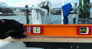
You can use a 2-foot level and a tape measure to estimate heel angle as weight is added. Using this method:
Heel angle = arcsin(inches heel at end of level/24).
Now that you have heel angle, you can determine GM.
GM = (weight)(distance from centerline to weight)/((displacement) x sin(heel angle))
Voila! Plugging the GM into the formulas for wind heel or passenger heel gives you an idea of your boat’s stability — with some disappointing limitations (read on).
Limitations
This simplified approach has its own limitations. Like the LPS or GZ Curve, it does not account for the effects of large waves and is thus is only appropriate for inland waters. The accidents it strives to reduce are water taxi and excursion boat capsizes. And it only applies to monohulls.
Most problematic, it does not apply to ballasted monohulls, because the effects of ballast are not felt until greater angles of heel are reached. Thus, while calculating the Inland Stability Standard for your boat can be an interesting exercise, it is best applied to monohull powerboats.
It’s likely that someone has already calculated your boat’s stability. Since 1998 all boats sold in the EU were required to have stability data calculated. Additionally, US Sailing ( www.ussailing.org ) maintains lists for one-designs and common boats. The easiest place to find certificates is through the Offshore Racing Congress ( www.orc.org ). Nevertheless, we know there are curious types who drawn to the idea of collecting their own numbers.
Heeling the boat with a line to the mast is one way to measure the forces required to heel your boat. And, although you can’t (and shouldn’t) roll the boat, you can lay it down pretty far if you have enough room.

This approach comes with a number of risks. If a line comes loose while the boat is severely heeled at the dock, the boat can snap roll up wards very rapidly, swinging wildly, slamming into the dock, and damaging other boats within range of the mast. Move the boat away from other boats and the dock.
Use the spinnaker halyard. It is designed for side loading and should be safely strong enough to put the mast in the water. A well-maintained rig should be strong enough to take this sort of use without damage. When estimating rigging loads, sparmakers and riggers will use this method to heel the boat to around 30-degrees.
If lines tied to docks are used to winch the mast down, remember that docks are not designed to take upward loads. We know of one sailor who, instead of going up the mast to retrieve a lost halyard, decided to heel the boat over until he could reach it. When the boat was heeled about 30 degrees, the dock decking lifted free and swung into the boat, ripping out lazy jacks and putting a kink in a shroud. The mast hit a neighboring boat, damaging that standing rigging as well. Of course, there were bad feelings all around.
The ORC uses this procedure to collect initial data to be fed into a computer program. The computer, using hull shape, appendage, and other details provided by the designer, then generates the entire stability curve. However, without the required software and precision measuring equipment, you’re not likely to learn anything useful that you can’t learn from some of the other methods described in the adjacent article. We recommend against attempting this without oversight of a rigger or engineer.
A partial plot ?
What about creating a partial plot of the righting moment. However, because you won’t be tipping the boat very far, you’ll only get a portion of the curve. When measuring the angle of heel, remember, righting moment = weight in pounds x distance from centerline to weight.
Gradually, heel the boat and enter the data into a spreadsheet that can be used to plot angle of heel vs. righting moment
You may be tempted to add leverage by adding weight to the spinnaker halyard or winching the halyard down to the dock. So long as you accurately calculate the forces in your equations, this can be done to create a more complete righting moment curve. However, the engineering can be tricky and mistakes expensive.
For a powerboat, you can learn much about stability with just 5-10 degrees of heel. On a sailboat we are more interested in the maximum righting moment, which probably occurs at greater than 45 degrees. We also need the angle of vanishing stability (AVS/LPS), the angle of no return, which probably occurs with the mast deep underwater.
During the first 15 degrees of heel, the righting moment curve of a wide boat with good form stability and a deep keeled boat with good roll-over stability will look very much the same. It is only after a boat is heeled to a greater portion of the angle of maximum righting moment, that it becomes practical to estimate the shape of the rest of the curve, and only then with very accurate data and complex analysis.
The simplified method does a fair job of predicting the stability of unballasted powerboats, but not ballasted sailboats. At 10-15 degrees of heel they are similar, but at extreme angles they are very different.
The Wolfson Approach
The Wolfson Unit of Southampton University has also offered a simplified calculation for sailboats requiring only the following information to yield the International Ocean Racing screening stability variable (SV):
- Hull draft in feet. This is not the full draft of the boat, but rather an estimate of the depth of the canoe body depth (DCB), not including the keel. Estimate this as 90-percent of the hull depth not including the fin keel.
- Ballast in pounds.
- Displacement in pounds.
- Beam overall in feet.
- Calculate the ballast ratio:
BR = ballast/displacement
- Convert displacement to cubic feet. For seawater:
VOL=Displacement/64
- Calculate the IOR screening stability variable (SV):
SV=beam^2/(BR*DCB* VOL^0.33)
- Finally, calculate the estimate angle of vanishing stability (AVS) in degrees:
AVS = 100 + 400/(SV-10)
This method makes some assumptions about the hull form, distribution of weight, and distribution of ballast, so we refer you to pages 6-10 of this more detailed treatment: www.westlawn.edu/news/WestlawnMasthead03_Sept07.pdf.
The greatest risk for 80-percent of sailors is not roll-over, but flooding. Unless the companionway is kept closed and tightly locked in all rough weather, as soon as a boat is knocked down there is a risk that water will pour in through the open companionway, and the boat will just go down. Clearly, it must be both strong and easy to open, under load, from either side (see PS October 2015 “ Bulletproof Companionways ”).
Some boats have enough beam and float high enough that the companionway remain dry in a knock down. This is a requirement of some classes, such as Open 60s.
Conclusions
While our experiments can give us a better picture of how gear stowage can impact stability, a complete GZ curve remains elusive for owners of mystery boats without certification or data supplied by the manufacturer. The best a DIY evaluation with weights can do is suggest initial stiffness under sail or power, the impacts of passenger or dunnage weight.
For a rough estimate of the angle of vanishing stability, the Wolfson method works fairly well with conventional boat designs (centerboards are problematic). If your Wolfson-derived AVS is greater than 120 degrees, rest easy. If the number is lower, you can improve it by stowing heavy things deeper, removing weight from the deck and rigging, and taking steps to prevent flooding in the event of a knock-down. The opposite is also true— a boat with inherent stability can quickly drop into borderline territory with poor gear stowage, open hatches, and top-heavy enhancements.
PS Online, “In Search of Stability,” PS Online July 2018. Former PS Editor Nick Nicholson dives into theory, www.practical-sailor.com/safety-seamanship/in-search-of-stability
PS June 2015, “Dissecting the Art of Staying Upright,” June 2015. www.practical-sailor.com/safety-seamanship/special-report-dissecting-the-art-of-staying-upright
PS September 2015, “Where Can I Find Boat’s Stability Curve?”, September 2015. www.practical-sailor.com/boat-maintenance/where-can-i-find-a-boats-stability-curve
Westlawn Inland Stability Test proposal, Test Proposal for monohull power boats. www.slideshare.net/NASBLA/stability-standards-and-testing-of-commercial-vessels-on-inland-waters-iss
Westlawn institute masthead vol. 1 Nos. 2 & 3, Two part discussion on stability by Dave Gerr, N.A. www.westlawn.edu/news/WestlawnMast head02_June07.pdf www.westlawn.edu/news/WestlawnMasthead03_Sept07.pdf
ORC Stability and Hydrostatic Datasheet, An explanation of ORC stability measurement. www.orc.org/rules/Stability%20and%20Hydrostatics%20Datasheet%20Explanation.pdf
RELATED ARTICLES MORE FROM AUTHOR

A Radio Lifeline for Cruisers

An Argument for Plain Nautical Language
Propane Leak: How to Detect, Locate and Fix
Leave a reply cancel reply.
Log in to leave a comment
Latest Videos

J Boats J/9 Sailboat Review and Boat Tour

3 Tips for a Dry Boat – DIY Boat Maintenance 101

Jeanneau’s New Rule Breaking Sailboat – Sun Odyssey 350 Boat Review

A Fiberglass Cleaning Boat Hack You Have To Try!
Latest sailboat review.
- Privacy Policy
- Do Not Sell My Personal Information
- Online Account Activation
- Privacy Manager

- Dealer login
- ENGLISH SVENSKA FRANÇAIS ESPAÑOL
- Technical information
- Press releases
- Online services
MAIN SHEET TRACK CALCULATOR
Enter values for boat and search matching travellers and tracks. The calculator suggests cars and tracks suitable for the calculated load.
| Righting moment at 30º heel. (RM30): | |
| Main sail foot length (E): | |
| Sheet point from mast (S): | |
| Unsupported length of track: | |
| Boat type: | |
| Approximate Main Sheet Load in kilogram: | kg |
| Required WY: | 0 cm³ |
| Required IY: | 0 cm |
Please note that the calculator may suggest incompatible cars / tracks. Make sure you select matching system.
CARS & TRACKS
| Item No | SubType | Profile | System | Wx (cm ) | Wy (cm ) | Height (mm) | Width (mm) |
|---|
- Find your retailer
- RM Calculator
- Furlex calculator
- Main sheet calculator
- Self Tack calculator
- Genoa car calculator
- Bowsprit calculator
- Crossbeam bowsprit calculator
- Upgrade your boat
- Block finder
- Seldén definitions
- Partner login

IMAGES
VIDEO
COMMENTS
RM CALCULATOR. Static righting moment the boat creates at 30 degrees heel. Please fill in the values to calculate an estimated righting moment. Calculate the Righting Moment of your boat, based on Displacement and other parameters.
A sailboat can increase its righting moment by adding ballast, increasing beam, or reducing sail area, and can reduce its heeling moment by reefing, easing sheets, or changing course. How does the wind speed affect the righting moment?
The righting moment (RM) of any vessel is simply = Displacement (delta) x GZ (lever) The relationship of the righting lever, GZ, to metacentric height, GM, is as you have shown: GZ = GM * Sin (ϴ) So, if you have the GM, you can easily calculate the GZ from the above equation and then the RM.
Righting moment (RM) stability curves for a 19,200-pound boat and a 28,900-pound boat with identical GZ values. Because heavier boats are inherently more stable, RM is the standard to use when comparing different boats (Data courtesy of Dave Gerr)
The NBS provides a way to calculate quite roughly what the momentum created by this crew "by band": δRM = 75*n*(3.4*B - 4.9*FS) Where n is the number of crew, B the breadth of the sailboat and FS freeboard in the vicinity of the mast. This gives us the righting moment induced by the crew.
Righting moment is the torque trying to return a boat into equilibrium, upright, when the boat is heeled. This may be the most important single factor affecting the boat stability. The magnitude of the torque can be calculated by multiplying the horizontal distance between the center of gravity of the boat and center of buoyancy of the ...
The results of a stability test gives a boat's righting moment, vertical centre of gravity (VCG) and limit of positive stability (LPS), which with the Stability Index (SI) can help determine a boat's eligibility to enter races categorized according to the WS Offshore Special Regulations.
Calculate the Righting Moment of your boat, based on Displacement and other parameters. Furlex calculator. Calculate the wire length and the length of the luff extrusion of your new Furlex system. Main sheet calculator. Use our calculator to select the correct unsupported high beam main sheet track. Self Tack calculator. Genoa car calculator.
Heeling a boat beyond 20 degrees is tricky, but if you can find boats with comparable design features and known GZ-Curves, you can visualize your own righting moment at various angles of heel, or at least roughly check the angle of maximum righting moment and the limit of positive stability.
Enter values for boat and search matching travellers and tracks. The calculator suggests cars and tracks suitable for the calculated load. Righting moment at 30º heel. (RM30): kNm. Main sail foot length (E): mm. Sheet point from mast (S): mm.